Publisher: Supplier of LED Display Time: 2022-09-19 17:05 Views: 2204
LED display debugging tutorial. The debugging of the LED display is divided into 3 steps: preparations before debugging, debugging the display area controlled by a single receiving card (usually a box) and debugging the large screen. Next, the editor of Liancheng will introduce you to the common LED display debugging methods.
Preparations before commissioning
2. Install the relevant software of the LED studio.
3. Confirm that the sending card is connected to the computer.
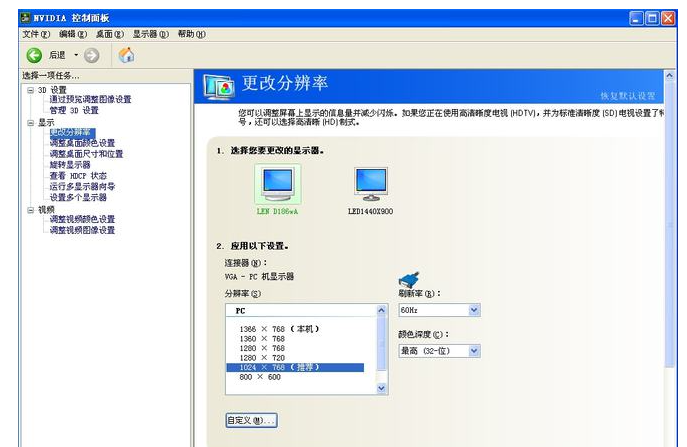
4. It is necessary to change the resolution of the computer graphics card and set the computer display mode. Take the NVIDIA graphics card as an example.
5. Right-click and select NVIDIA Control Panel. Enter the following screen, select the option to change the resolution in the left window, so that the resolution of the computer graphics card is the same as the resolution of the sending card. .
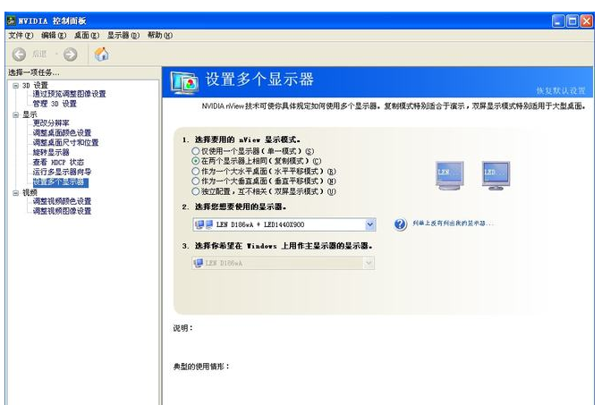
b. Select the option of setting multiple monitors as shown in the figure below, and select the copy mode, as shown in the figure below.
6. Connect the network cable between the sending card and the receiving card in the computer, and connect the power supply and cable of the display.
7. Debug the display area (usually a box) controlled by a single receiving card (take LCF P16 display screen as an example, a single box of LCF display screen is 64×48). The cable connecting the riser card to the display must be correct, otherwise the intelligent setting will not be able to correctly identify the display. When entering the setting interface, you should carefully watch the changes of the display screen while operating, and the display screen will prompt you all the operation steps.
8. Double-click the desktop LED setting to enter the LED setting interface.
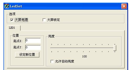
9. Click to set parameters and enter the password 168.
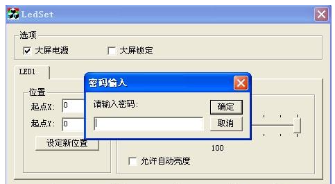
10. Enter the setting interface, display mode adjustable resolution under the sending card (this resolution needs to be larger than the resolution of the large screen), and then click the receiving card.
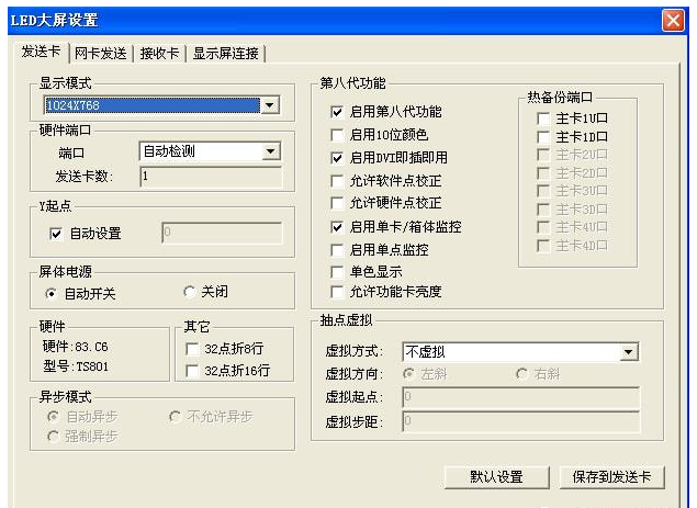
11. The interface shown below will appear.
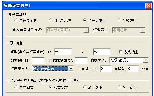
12. Click Smart Settings to enter Smart Settings Wizard 1, as shown below.
a. Display type: select the number of full-color real images;
b. Points of module information: input the number of lamp beads controlled by a receiving card (LCF P16 receiving card controls a box of 64×48, then input 64 in X and 48 in Y);
c. The number of data interfaces in the module information: the number of cables that need to be drawn out for the receiving card;
d. The number of data lines per port in the module information: The number of data lines per port is different for different models of displays. (Generally: if the display screen uses a 16-pin cable, the number of data lines per port is 1; if the display uses a 20-pin cable, the number of data lines per port is 2; if the display uses a 26-pin cable, the number of data lines per port is 2. The number of data line groups per port is 3).
e. Data type: Red and green (blue) separate.
f. Decoding method: Different types of display screens have different decoding methods (generally, all indoor screens are decoded by chip 138; outdoor screens P16 and P20 are static and do not need to be scanned)
g. Other options are selected by default.
13. Click OK to enter setup wizard 2, and watch the display, watch states 1 and 2, select the correct display state, and click Next.

14. Watch the led display, watch states 1 and 2, select the correct display state, and click next.

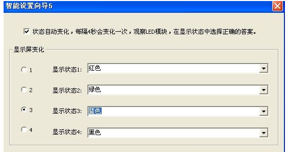
15. Watch the display, watch states 1, 2, 3, 4, select the correct display state, and click Next.
16. Watch the display and select the number of bright lines and interval lines (including one bright line), then click Next.
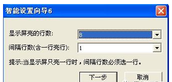
17. Enter the following interface.
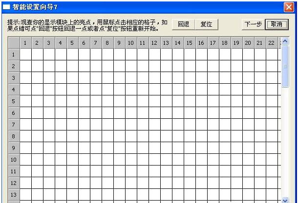
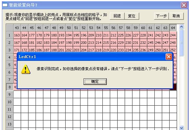
18. Position the display screen to see which one is lit on the display screen, and then click the corresponding point on the computer. After each point is completed, the display screen will prompt the next point, until the following interface appears, indicating that the pixel point recognition is completed, click OK, and then click Next.
19. The following interface appears, click OK to observe whether the display screen is displayed correctly (the correct display screen should be the upper left corner of the computer desktop).
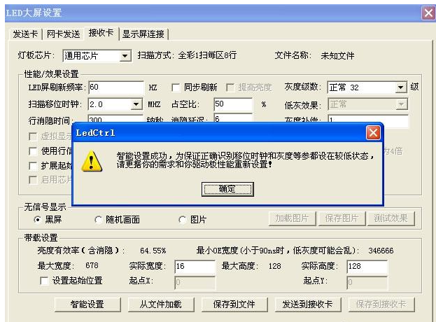
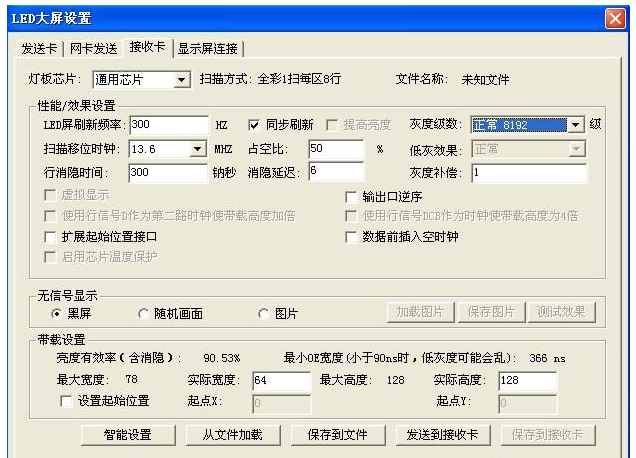
20. Set the refresh frequency and grayscale parameters you need according to the display screen and send them to the receiving card. The parameters shown in the figure below are the reference parameters (note that the maximum width in the load setting must be larger than the actual width, you can change the refresh frequency by changing the , gray constant, scan shift clock to change the maximum width), pay attention to save the set file for the next call.
Debug a large screen (take LCF LED display as an example):
1. Double-click the desktop LED setting to enter the LED setting interface.
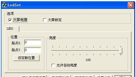
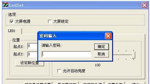
2. Click to set parameters and enter the password 168.
3. Enter the setting interface, and then tap Display connection.
a. Setting method: select standard display, do not need to enable smart connection.
b. Number of Displays: 1
c. Type: full-color real pixel screen; number of horizontal cards: 10; number of vertical cards: 8.
d. After the above steps are completed, select a small box (representing a cabinet) as shown in the figure below, and then set its parameters.
e. The gamma value and screen brightness are as shown above.
f. Main line: select the No. 1 sending card U line (1U) (this line corresponds to the network cable jack on the sending card on the computer that is far away from the sending card dvi cable)
g. Breakout: Both are 1.
h. Serial number: The serial number of the first box (receiving card) connected from the computer network cable is 1, the serial number of the first box connected to the second box (receiving card) is 2, and so on, the last one The serial number of the box (receiving card) is 80.
i. Width and height: the number of lamp beads in a box (a box in Ya'an is 64×48, so the width is 64 and the height is 48).
j. The card brightness and those not mentioned are subject to the default, no need to change.
4. After setting, click Send to Acceptance Card, observe whether the large screen is displayed normally (the normal display of the large screen should be the upper left screen of the computer desktop) and save it to a file for the next call.
The above is the ed display debugging tutorial compiled by the editor of LCF. I hope it will be helpful to you. At the same time, you are welcome to correct or add. LCF is a world-leading provider of LED display applications and solutions, as well as a national-level specialized, special, and new little giant enterprise. The main business covers "smart city", "cultural tourism business performance", "commercial display project", "content technology" four sections, with the world's leading automated production equipment and modern post-doctoral research laboratory and perfect sales and services team. Friends who want to buy LED display can also contact us, LCF LED display manufacturer, a big country brand, trustworthy!
