Publisher: Supplier of LED Display Time: 2024-11-19 13:43 Views: 1074
LCF editor will bring you in this article LED display assembly detailed tutorial.
First, preparation
(A) materials and tools to prepare
1.Materials
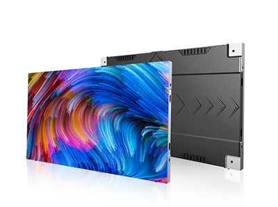
LED display module: according to the size and resolution of the required display to choose the appropriate number of modules. Ensure that the module is not damaged and the lamp beads look normal.
Power supply: according to the power requirements of the display to choose the matching power supply, generally 5V, 12V and other different specifications, and to consider the power redundancy of the power supply.
Control card: choose the control card that matches the specifications and functional requirements of the display, such as synchronous control card or asynchronous control card.
Cable: Used for the connection between modules, to ensure that the length of the cable and the interface type is appropriate.
Power cable: used to connect the power supply and various components of the display, the wire diameter should meet the current transmission requirements.
Profile frame: used to build the frame of the display, to ensure its strength and stability, and at the same time, to consider the aesthetics of the frame.
Screws, nuts and other fixed parts: used to fix the module, power supply, control card and other components.
2.Tools
Electric drill: Used to make holes in the bezel to facilitate the installation of screws.
Screwdriver: including cross screwdriver and one-word screwdriver, used for screwing screws.
Sharp-nosed pliers: Used to clip small objects and tidy up the wires.
Multimeter: used to detect the power supply voltage, check whether the circuit is on or not.
Scissors: used to cut the wires and power lines to the right length.

(B) Site preparation
Choose a clean, spacious and flat assembly site and avoid operating in a humid or dusty environment to prevent damage or malfunction of the display components. At the same time, make sure that the venue has a stable power supply and that there are no strong sources of electromagnetic interference around.
Second, bezel assembly
1. According to the design size of the display, place all parts of the profile frame in the assembly site. Use electric drill to make holes in the connection parts of the frame, and the size of the holes should be matched with the screws.
2. Connect the sides of the bezel with screws and nuts to form a rectangle or a frame of the desired shape. During the connection process, use a right-angle jig or other measuring tool to ensure that the angle of the frame is 90 degrees (for rectangular frames), to ensure that the entire frame structure is regular. After the connection is completed, check the firmness of the bezel and further tighten the screws if there is any looseness.
Third, power installation
1. Determine the installation position of the power supply in a suitable location on the frame. Generally choose one side or corner of the bezel, to facilitate the connection of the power cord and heat dissipation. Use screws to fix the power supply on the bezel.
2. Connect the power cord to the input port of the power supply and make sure the connection is firm. Then, organise the power output cable ready for connection to the display module and control card. Use a multimeter to check whether the power supply output voltage is normal. If the voltage is abnormal, check whether there is any problem with the power supply and power cord.
Fourth, control card installation
1. Select the installation location of the control card in the frame, generally near the power supply and easy to connect with the computer or other signal sources. Use screws to fix the control card on the frame.
2. Connect the control card to the power supply to ensure that the power supply is normal. Then, connect the control card with the external signal source (such as the computer's network cable or USB cable) to prepare for the subsequent debugging work. At the same time, according to the instructions of the control card, set up the basic parameters of the control card, such as the resolution of the display, scanning mode and so on.
Fifth, module installation
1. Start installing the module from one corner of the display. Place the first module in a suitable position inside the frame, and use screws or clips (according to the installation method of the module) to fix it on the frame. Pay attention to the orientation of the module to make sure it is in the same direction as the designed display.
2. Take a cable and connect one end to the output connector of the installed module and the other end to the input connector of the next module to be installed. When connecting the cable, make sure the connector is fully inserted to avoid loosening. Repeat this step to install the modules one by one and connect the wires sequentially to form an array of modules. During the installation process, constantly check the flatness of the module to avoid the occurrence of unevenness of the module.
Sixth, line connection and finishing
1. Connect the power output line to the power input interface of the display module, and reasonably allocate the power line according to the power requirement of the module and the output capacity of the power supply, to ensure that each module can obtain a stable power supply. Use a multimeter to check whether the power supply voltage of the module is normal.
2. Organise all the wires and power cables to avoid messy lines. You can use cable ties or cable channels to fix the lines on the bezel to prevent the lines from being pulled or damaged during use. At the same time, pay attention to the direction of the lines to avoid lines interfering with each other or affecting the heat dissipation of the display.
Seventh, preliminary commissioning
1. Switch on the power supply and observe the indicator status of the control card and display module. Under normal circumstances, the power indicator should be lit, the control card's data transmission indicator should be flashing regularly. If the indicator status is abnormal, according to the indicator's prompt information to troubleshoot the problem, such as checking the line connection, power supply, control card settings and so on.
2. Use the software accompanying the control card to send a simple test image or text to the display to check whether the display can be displayed normally. If there are display abnormalities, such as splash screen, lack of colour, non-display and other problems, gradually check whether the wiring connection is correct, whether the module is damaged, whether the control card parameters are set accurately, etc., and make adjustments and repairs accordingly.
Eighth, the final check and perfect
1. carry out a comprehensive inspection of the assembled LED display, including whether the appearance of the display is smooth and beautiful, whether the frame is firm, whether the line connection is reliable, whether the display effect is normal.
2. If problems are found, timely processing and improvement. After ensuring that the display is all normal, the tools used in the assembly process and the remaining materials for finishing and storage. At this point, the assembly of the LED display is complete.
Through the above detailed steps, you can successfully assemble an LED display.LCF reminds you: during the assembly process, operate carefully and strictly follow the instructions and relevant specifications to ensure the quality and performance of the display.
The above is LCF editorial to you to put together a detailed tutorial on the assembly of LED display, I hope to help you, while you are welcome to add or correct.LCF is a collection of R & D, intellectual, sales, operation, service in one of the national speciality and speciality of the small giant enterprises, national high-tech enterprises. If you need to buy LED electronic display friends can also directly contact the LED display manufacturer LCF, the big country brand, trustworthy!

